Series Notch Filter Designer / Calculator Help
Use the Series Notch Filter Designer.
Series Notch Filters are designed to dampen driver resonance at its resonance frequency (fs). Drivers can produce 10db (or more) peaks at their resonance frequency. This filter will remove that spike. This filter is used mostly in mids and tweeters. With a woofer large inductors are usually required which are costly and have a large resistance which causes its own problems. If using a ferrofluid (or some other magnetic oil) cooled tweeter, then the resonance should already be damped and the filter is probably not necessary. Also, if the crossover point is 2 octaves or more above the resonance frequency, and a 2nd order or greater crossover is used, then the filter is probably not necessary.
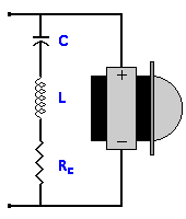
A Series Notch Filter is simply a capacitor (C), inductor (L) and resistor (Rc) all in series, in parallel with the driver. Sometimes, a series notch filter is called a LCR filter, because of the L, C, and R components.
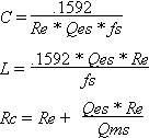
Re = Driver DC Resistance in Ohms
fs = Driver Resonance Frequency in Hz
Qes = Driver Electrical Q
Qms = Driver Mechanical Q
Use these formulas if you don't know Qes and Qms.
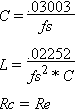
When using the second set of formulas, experiment with different values of Re in .5 Ohm increments. This assumes you can measure frequency response. Otherwise, try to use a driver that you know the Q values for. If designed properly, a series notch filter usually does not require testing or experimenting. It should work properly on the first try.
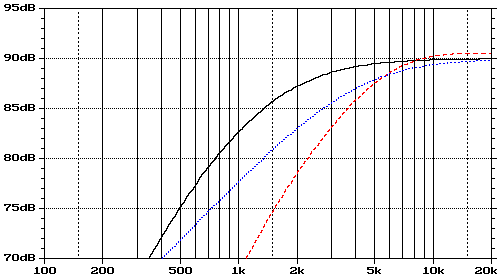
Example: Say you have a tweeter with a Re of 8 Ohms a fs of 1000 Hz, and want to use a first order (6db/octave) Butterworth high pass crossover at 4000 Hz. The tweeter does not use magnetic oil cooling, and the crossover point is two octaves from the resonance frequency. The driver resonance will affect the frequency response as seen below. The first order crossover is just a 5 uF capacitor in series with the driver.
Actual driver response with no crossover
Desired driver response
Actual Driver response with crossover
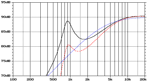
With and without the crossover, there is a large spike in frequency response a the crossover point. Using a fs of 1000 Hz and a Re of 8 Ohms, with the second set of formulas you get C = 30.03 uF, L = .75 mH and Rc = 8 Ohms.
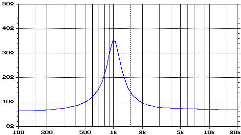
Think of the capacitor as a HPF and the inductor as a LPF. This creates a small bandpass circuit where the current will flow through the resistor. Outside of these bandpass frequencies, the resistance of the series notch filter and the driver is simply the resistance of the driver. In the notch, the resistance is much higher, depending on how much you want to dampen the resonance.
Impedance curve of the series notch filter only
When the series notch filter is used with the driver, you get the frequency response shown below. The reason the combined crossover & series notch filter response curve is below the desired response is because the roll-off of the driver and crossover are summed.
Actual driver response with the series notch filter
Desired driver response
Actual Driver response with the crossover and the series notch filter